Tuesday, May 10, 2011

No-Name Evolution

The No-Name Industrial Park track plan and indeed the layout itself has gone through a series of identity changes, geographical relocations, time periods, and just about any other change you can think of.  I'll describe a few of the more interesting points along the way.

I started off knowing I wanted some focus on industrial switching, but I was also thought I wanted some continuous running.  I had originally been thinking about modelling the 50s, the default time period of model railroading.  Once I realized how big an O scale turntable was going to be I decided steam power was not a wise use of my space.  I slid the time period ahead to the late 60s and early 70s.  The location was set in the area of western New York where I grew up.  So my first serious O scale plans were called the Elmira Industrial, placed in Elmira, NY circa 1970.

The Elmira Industrial, an early version
I managed to squeeze in a double track mainline, some staging, a small yard, a couple industries in Elmira itself, and an industrial branch.  At the end of the industrial branch was Thatcher Glass, a large glass bottle manufacturer.  And near the end was an interchange with the PRR.  Even at the time I drew the plan I knew better than to have a duck under - I just don't like them.  So I thought perhaps a drop leaf or something might do.  But that compromise, combined with the short length of the yard tracks, staging, and the over crowding of the industrial area made me have second thoughts.  When I started thinking about the tiny yard and how many cars it would have to handle in how many different blocks I realized the plan was out of balance with itself.

The next iteration of the plan did away with the duck under and therefore the mainline as well.  It still had staging though.  The general idea was that the mainline (which actually would exist in dummy form on the front edge of the layout near the yard throat) was implied, and trains would pick up and set out blocks in the yard.  In reality that meant and engine shoving a cut of cars in from a staging track and returning with a different block.  There was staging for east and west bound EL traffic (the railroad being modelled was the Erie Lackawanna), Lehigh Valley (which ran up from Sayre PA through Elmira to Horseheads, interchanging with the EL in Elmira), and a couple Pennsylvania tracks (PRR had trackage rights on the EL through Elmira).

The Elmira Industrial, a later version
The larger yard in both length and breadth would easily accommodate handling the inbound blocks, and classifying for various industries and the 4 different outbound blocks.  Thatcher Glass still occupied what you will recognize as the peninsula devoted to the N scale Palmer Industrial Park now, but it's based on a slightly earlier configuration of the prototype before the newer set of warehouses got built.

At that point construction got seriously under way, and the bottom part of the plan along the wall was built, plus a little bit up the left and right side walls.  I hand laid code 125 rail on wood ties, using Old Pullman turnout kits.  It was exciting - nothing beats the thrill of the first train run on hand laid track.

First train runs!
After the initial euphoria wore off I started to notice a few hiccups with the Old Pullman turnout kits and in the process of tinkering with them to improve them I learned more about turnouts and what to keep an eye out for.  Some inspection revealed that the one curved turnout kit I had purchased would require so much work to get the closure rails to properly line up with the frog, etc. that it might just be easier to start from scratch.  (I believe I may have ordered my turnouts at a bad time in Old Pullmans transition between owners, I would not assume my experience from some years back is any indication of their current product which I have heard good things about.)  If you look at the trackplan closely you'll notice that there are 6 or 7 curved turnouts in the yard throat area that are critical.  Any flaws in this area would make the layout a nightmare to operate.  And you'll notice that there are a lot of turnouts in general.  Doubts about my ability to get this layout operational began to set in.

Around this time two other things changed.  I started doing a lot more rail fanning, and began to get enamored with present day railroading.  (I don't use the term "modern", because various people use "modern" to refer to anything from a 1950 F unit to a 2010 genset.)  And Atlas starting making good quality O scale turnouts.  I started thinking about how to re-arrange the plan to use Atlas O turnouts.  Without the curved turnouts in the yard throat, the yard couldn't be nearly big enough to support the general operating scheme.  Major changes seemed to be in order.
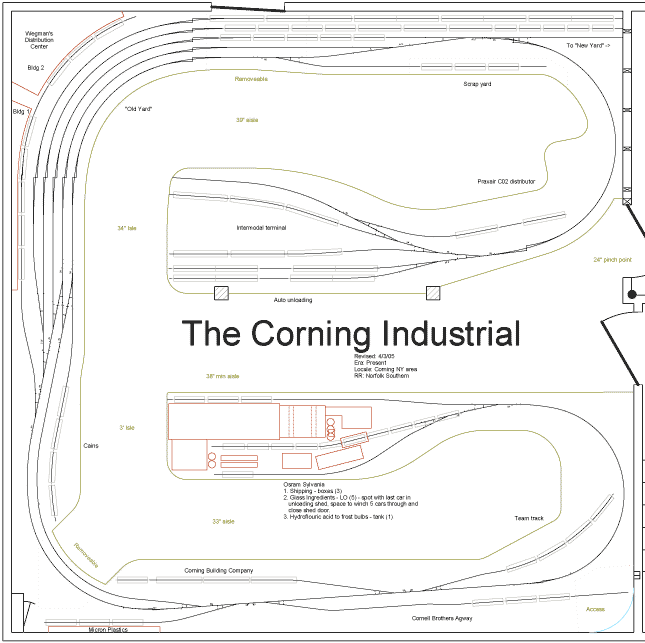
The Corning Industrial
The result was the Corning Industrial plan.  Corning is about 10 miles west of Elmira in real life, and the former EL has gone through the Conrail stage and is now the Norfolk Southern.  This time the mainline was not even hinted at on layout, it was "over there" a the other end of the yard just past the top right corner of the room.  There was also no staging.  The assumption is that through trains, one eastbound and one westbound, would pick up outbound blocks and set out inbound blocks "overnight" - in other words between operating sessions.  At the start of an operating session two of the yard tracks would have the two inbound blocks on them.  A third track allowed for some storage.  The remaining two tracks were the through track and the runaround.  Not many tracks in number, but all pretty decently long, and I figured there would be enough space to sort things out without getting too crowded.  The parts of the layout with track already laid stayed untouched, with one exception - the second track and industry in the middle of the wall got removed in favor of a single larger industry.  The one remnant of the original plan lingers to this day in the No-Name Industrial - the jog in the middle of the track.  There's still a glass plant on the peninsula, but this time it's based on the Osram Sylvania plant in Wellsboro, PA.  The area formerly occupied by the yard was now planned to be an intermodal area.  Two tracks for auto racks, two tracks for intermodal flats.

Norfolk Southern uses big power for everything, and with the length of cuts I expected to be dealing with to sort out the yard it seemed like a two unit consist would not only be prototypical, but necessary.  I bought two Atlas O B40-8s.  A couple sample intermodal flats, more articulated auto racks than I care to admit, and I figured I was in good shape.  I built the left and top wall parts of the plan, and got started on the curve around into the intermodal area.  Things went considerably faster with flextrack and ready to run turnouts.

Two thing went wrong.  First, although it seems like there is enough track to handle everything, once I started actually moving cars around I started to realize that while there was enough track for everything to be on without over crowding at any given point in time, there wasn't necessarily a way to move a cut from point A to point B without either pulling long cars through the tightest curve on the railroad (36" radius going to the glass plant), or breaking the cut in half and doubling it through the crossover between the runaround and the through track.  My long yard tracks which had seemed so nice and spacious on the plan were turnout out to have moved the throat so far around that I didn't have enough lead!  Changes were called for.

The second thing that went wrong is the B40-8s themselves.  My first Atlas O engine was an SW-8 which runs like a dream.  (I don't really count the little plymouth diesel in the above photo - an ancient Atlas unit I picked up at a white elephant table.)  Very smooth starts and stops, good smooth slow speed running.  The B40-8s on the other hand simply would not sustain any speed between 0 and 3 or 4 smph with a standard decoder - you had to either be starting or stopping.  Once you got past the initial jerk into motion they ran pretty smoothly.  But since my whole operation is switching, starting and stopping is very important.  I could not make them run what I considered to be acceptably smoothly while starting and stopping slowly.  I got reasonably close with two zimo MX69S back-emf decoders, one for each of the two motors in each unit.  There were still subtle but irritating jerky motions though.  I bought an SD40 when they came out and were reported to have fixed the running problems of the B40-8s, however I found it still suffered from the same fundamental problems.

The Corning Industrial was now teetering on brink of survival, and the thing that pushed it over the edge was the arrival of the Atlas MP15 - a new switcher which had all of the same operational qualities as the original SW8 in a more modern and highly detailed package.  The Corning Industrial got a major mission change - sparser, fewer cars to be handled per op session, and it would be considered to be the end of an industrial branch.

The Corning Industrial last gasp
I did some mockups, pulled up a couple tracks, and played around with the idea for a while.  But in the end I came to the conclusion that a large part of my problem all along had been over reaching - planning something larger than I could reasonably build and maintain, and cram too much operation onto it.  Drastic measures seemed to be in order. I decided to keep just the left and bottom sides of the plan, and rip out everything else.  Well, except for the peninsula which I decided to leave in place in case I ended up wanting to put some staging on it.  It wasn't until later that I got the idea of building an N scale layout on it.

The No-Name Industrial Park
The power tools came out, large chunks of benchwork were removed, lots of homabed glued into nicely easemented curves around the top left corner was chiseled off and construction got under way on what I hope is the final reconfiguration.  I also had a lot of rolling stock and a few engines to unload, which turns out to be a lot harder than you would think.  I've got a lot of stuff on consignment at a hobby shop, I donated some stuff to a local club, and I gave some stuff to a couple friends who used it to set up their own modular O scale switching layout. It's apparently relatively easy to sell used HO scale equipment, and N scale equipment is so small you can store a whole railroad's worth in a small drawer.  But with O scale, it was taking LOTS of space in the basement, and let me tell you trying to fit 12 O scale articulated auto rack boxes into the back of a car to take somewhere to sell is NOT easy, and you won't get anything else in that trip.  Just something to think about if you ever find yourself in the mood to buy lots of equipment up for a planned O scale railroad.

I'm pretty happy with the end result.  Operations are interesting even though I don't have the full complement of boxcars necessary for Northeast Container yet (I'm being cautious about buying more than I need, a few at a time until it seems like enough is the plan).  An op session takes somewhere between 45 minutes and 2 hours, depending on what needs to be done.  The layout feels much less crowded, which is nice too.  The smaller size also makes a little more likely that some day I might actually get some scenery done.

I've come to realize that although I really enjoy operation on some larger layouts with large yards and long mainlines, it's not what I want for my own layout.  I'd like to think I've arrived at a good lasting plan, but of course there is always that cynical little thought that pops out saying "yeah, right".  Time will tell one way or the other.

Monday, May 9, 2011

Mocking up the Palmer Industrial Park

It's been a long time since I built anything in N scale - I've been in O scale for a number of years now.  I was concerned that although my plan for an N scale Palmer Industrial Park looked good on paper, I might be surprised when I built it.  Since the benchwork was already done (re-purposed from an aborted O scale plan) I decided to mock up the N scale plan full size in place.

Trans Plastics mockup
The above photo shows my mockup of the upper side of the trackplan (see below).  The black magic marker scribbles around the Trans Plastics tracks are where the paved area will be.  The mockup is quite crude - just sticks of flextrack laid over each other and the switches are merely implied.  Still, it's enough to get an impression of what the layout will look like.  The wood sticks to the right are where the backdrop will be.


I made the mockup by printing the track plan out full size.  The first step for a full size printout is to add grid lines to the cad drawing spaced closely enough to ensure that there is at least one grid intersection on each printed sheet so you can slide them all into the right positions.  Since I was going to print on legal (8.5x14) paper that meant mostly 1 foot intervals with some lines at 6" intervals.  Planning is key to get the lines in the right places.  Or alternatively you could just use a smaller grid (say 3 or 4" spacing) and not worry about exactly where the sheets fall.  I printed enough sheets to get all of the interesting track, but not necessarily the pure straight stretches - I connected those up with a ruler and pencil later on.  In order to keep from mixing the sheets up, I numbered each grid line on a small scale printout of the plan, and then number the corresponding grid lines on each full size sheet as it came off the printer.

The next problem is getting a full size version of the grid drawn on the benchwork.  The plywood on the peninsula has at least 2 prior O scale plan variations drawn on it in heavy pencil lines, so trying to add a grid on top of that seemed to leave a lot of room for confusion.  I have a 3 foot wide roll of paper left over from the days when I had access to a large format printer on a BYOP basis (bring your own paper).  The layout happens to be exactly 3 feet wide.  So I rolled out paper down the length of the layout and securely taped it down to give me a nice clean surface to draw the grid on.  I used a laser line projector to get a reference line down the 16 foot length of the layout, marked it at intervals, then used my longest straightedge to pencil it in.  A piece of string would have done just as well (and in fact that's what I've used in the past), but I am a bit of a gadget freak and a project that uses a laser is inherently cooler than a project that uses a string.  A carpenters square got me the cross lines on the grid.

The last step in getting the full sized plan was to number the full size grid the same way I numbered the small scale one.  Then carefully position and tape down each printed sheet.  It's hard to get a photo that shows the lines well.  This one is heavily tweaked to bring out the contrast.  The printed sheets are around the edges where the track is, near the center is the straight grid on the roll paper.  The heavy black teardrop in the center is a mockup of where the backdrop will be.


Mockup with printouts only
A single line representing track, even printed full size, still doesn't make it easy to get a sense of what the finished layout will look like.  To get a better idea, I used double stick tape to stick down flextrack along the lines.  I trimmed and used rail joiners to make the main track in the park runnable, but all the other tracks are just stuck down in the right place.  Making the main track operable let me test pulling and pushing 25 car cuts around the 16" radius end curve.  And it let me get a real sense for how long certain things would take, such as doing a runaround, then shoving to Maple Leaf at a scale 10 mph (the top speed permissible in the real Palmer Industrial Park).

Here's a few more photos of the mockup.  First is an end view taken from a similar angle as the black and white photo above.

End view
Next is a shot of the other side of the layout.  This shot shows the lead (nearest the edge), the runaround, the main track with 20 50 foot boxcars positioned between the clearance points for the runaround switches - the plastic pellet cars in the foreground would be sitting on the near switch - and the Quaboag track.  The two red cars at the far end of the Quaboag track are 75 foot center beams in the lumber unloading area.  You can make out the two Quaboag building mockups, although it's not easy since I used white paper and foam core for them they don't exactly stand out from the white paper on the layout surface.

Lead, runaround, and Quaboag
Finally here's a photo of the Maple Leaf Distribution mockup, again a little hard to see in the photo because everything is white.  The photo does give you a sense of the size of the building, which is about 46" long.  Should be very interesting to switch, especially if the second track isn't stuffed full.

Maple Leaf Distribution
I'm now much more confident that my plan will actually produce something that looks like I expect.

Current state of the layout is pretty much as shown.  I've boxed up and stored all the rolling stock, and unstuck and stored the track.  The next step is to cut out holes in the center of the paper where backdrop vertical supports will go.  And then carefully roll up the paper will all the little sheets still taped in the right places.  Once the backdrop supports are fastened to the plywood, I'll cut and position the 2" thick foam down each side, leaving just a little space to slip the backdrop in.  With the foam glued down, the tricky bit will be to roll the paper plan back out, dropping the holes down over the backdrop supports, and get it re-located properly and any errant sheets repositioned and secured.  A pounce wheel should make it easy to transfer the track center lines from the paper to the foam.  Once I'm sure that's right, the paper gets rolled up again (carefully, just in case), and I can go over the pounce wheel marks with a marker to make them more easily visible.  Then mount the backdrop, and lay track.  Sounds easy... but time will tell.

However, before I take the next steps on the N scale layout I'm taking the time to get the O scale layout running again.  You may have noticed stuff piled on it in the photos.  Those piles were on the future N scale layout before I started the mockup.  Now they need to be dealt with for real.  There's nothing like having a running railroad to keep the inspiration level up.

Tuesday, May 3, 2011

The Palmer Industrial Park

I'm in the early stages of building an N scale layout representing the Palmer Industrial Park, served by the New England Central railroad.  Why a separate second layout?  I got to thinking about it because I found myself wanting to model some larger industries than could be fit in my space in O scale.  I also wanted to keep the O scale switching layout, which meant the remaining available space was too small to model larger industries in HO scale.  Hence the choice of N scale on a second layout.

In addition to modeling larger industries, I also wanted to get more of a prototypical feel to the track arrangement.  I used # 5 turnouts on my O scale layout - unrealistically sharp.  After spending some time with satellite photos measuring angles of switches on industrial track I was interested in, I came to the conclusion that # 10 switches were just about right.  I verified this with a tape measure on a field trip to a location with a switch in a parking lot I could measure the frog taper on.

In real life the Palmer Industrial Park is in Bondsville, MA, just north of Three Rivers and Palmer.  It's worked by a local out of the NECR yard at Palmer.  I'll write a post about the prototype at some point, but for now suffice it to say that I couldn't squeeze in an exact replica of the park.  So I took all the interesting pieces, shuffled them around to fit, and used a little imagination.

Trackplan for the Palmer Industrial Park
The peninsula is 16 feet long, and 3 feet wide at the left end.  It's slightly odd shape at the right (wall) end lets it fit between the door and the O scale switching layout.
Edit 1/18/2015: I realize I neglected to include a few details here.  All turnouts are #10. The big curve around the end is 16" radius, the minimum radius everywhere else is 24", and most curves are much bigger radius than that.  The easement offset is 0.25".  Track and switches are Atlas code 55.
The park has a long lead which comes in from the NECR main at Barrett's.  The lead is the track next to the aisle marked Lead on the track plan above.  The runaround and it's tail track head off back to the right and disappear into the weeds - the presumption is there used to be more industry over there but it's now abandoned.  The runaround holds 20 50 foot N scale cars.  One option I considered during planning was to put the runaround on the lead and eliminate the "extra" track.  However with the potential for 15-25 inbound cars and 15-25 outbound cars in a session the additional space will come in very handy.

The only industry on the lead side of the peninsula is Quaboag Reload (pronounced "kway-bog").  Quaboag is patterned after a combination of the now defunct Quaboag Transfer that was a large customer in the real Palmer Industrial Park, and Wildwood Reload - an industry on the Massachusetts Central RR in South Barre, MA.  Pretty much anything that needs to move between rail and truck can show up here.  Common loads will be lumber on centerbeams, wood pellets, paper rolls, and building materials in box cars, pipe in gondolas, sheet steel in coil cars, etc.  The first warehouse on the lead is completely enclosed, the second is open at the track end.  The large areas in between and at the end of the track are for unloading lumber, pipe, etc. that don't need indoor storage.

The industry just around the corner is initially going to be Cains - an N scale version of the same industry I have on my O scale layout.  What I really want to put there is another industry from the real Palmer Industrial Park - American Dry Ice.  However there are no N scale CO2 cars available at the moment.  Atlas makes some nice vegetable oil funnel flow tanks, so it's Cains for now, and if/when CO2 cars appear I'll replace Cains with American Dry Ice.

The next industry is Trans Plastics.  In the real Palmer Industrial Park this industry is at the end of the park track, but it seems to fit better when I've put it in my available space.  Trans Plastics has space for around 20 covered hoppers loaded with plastic pellets.  As with the real one when it was still in business, the industry will be close to full most of the time, but only release and receive 2-4 cars a session.  Since there are a lot of different grades of plastic in the various cars that get used up as needed, the cars released may be scattered around, so this industry will be interesting to switch.

The final industry is Maple Leaf Distribution.  In real life Maple Leaf now has 3 pairs of tracks serving 18 doors.  Before their addition of a few years ago, it was 1 pair of tracks serving 10 doors.  I plan to compress reality a bit to make the "original" building have 7 spots spaced for 50 foot cars (like the original 10 on the real thing), and the "new" building on the same pair of tracks have 3 spots for 60 foot cars (like the new spots on the real thing).  Maple Leaf receives lots of paper rolls and a number of other commodities in box cars and ships them out by truck.  They also receive recycled paper by truck and ship it out by box car.  They generally assign cars to doors to minimize movement through the warehouse.  There may also be respots (a car not completely unloaded needs to be moved to pull/spot another car, then returned to where it was).  A car that was on the outside track and not completely unloaded may need to be respotted at the same door on the inside track.  The combination of specific door assignments, respots, and the two tracks should make for some very interesting switching.

The main park track continues past Maple Leaf and fades into the weeds at the wall.  The almost 20 car lengths between the Maple Leaf switch and the wall will provide needed space for sorting cars and stashing outbound cars out of the way.

The current state of the railroad is bare benchwork, with a full size trackplan tapped to it (more on that later).  The benchwork is actually a re-purposed section of what was originally planned to be a larger O scale layout.

Monday, April 25, 2011

The No-Name Industrial Park

The No-Name Industrial Park is my O scale switching layout.  It represents a small industrial park somewhere in eastern/central Massachusetts.  I've had so many different ideas of what I want to call it over the past year that I've decided to just ignore the naming problem for now.  Therefore for the time being the layout is known as the No-Name Industrial Park.  The park is operated by a switching service - also unnamed as of yet.  The park lead serves as an interchange track with the nearby railroad - also unspecified (but which will be either CSX or Pan Am Southern).

Trackplan for the No-Name Industrial Park

The room is almost exactly 21 feet on each side.  For perspective, that's 1008 feet in O scale.

The connection to the outside world is in the lower right, where the tightest curve on the railroad (36" radius) curves out into the aisle where it says "interchange".  Following the main track from there, the first switch you come to is a 3 or 4 car storage track for Northeast Container.  Next is the switch for Midstate Recovery Systems, a construction and demolition debris recycling business.  Next is the switch for Northeast Container itself, followed by another short storage track.  Around the lower left corner is the runaround, which can hold 9 or 10 cars.  The runaround is a slightly more forgiving 44/48" radius.  Continuing up the left wall, the next switch is for Tighe Warehouse, and then a transload track.  The final switch is for Cains Foods.

I got the idea for a switching service operating the park from SMS Rail Lines, a company that operates several industrial parks in New York, New Jersey, and Pennsylvania.  It's a fascinating operation - you can spend quite a bit of time poking around their web site and studying google/bing maps satellite and aerial photos of the parks they serve.

Power for the park switching service is an MP-15 purchased second hand from CSX and given a patch paint job.  Or at least that's the plan - currently the Atlas O MP-15 sports factory fresh CSX paint.  The MP-15 is generally kept up near the Cains switch, where there's a small trailer office.  The switching service keeps someone on hand to respond to customer requests whenever needed.  So an operating session might be as simple as pulling an empty/load from a customer to replace it with a fresh car from storage, as complex as finding a dozen inbound cars on the interchange track that need to be shuffled into position, or anywhere in between.

Northeast Container is based on the Temple-Inland plant in Biglerville, PA served by the Gettysburg Northern RR.  The plant makes boxes.  It receives boxcars of pulpboard and an occasional hopper car of starch.  Some of the empty box cars get re-spotted at the outside dock to be loaded with scrap cardboard.  Jack Hill describes it here on his blog.  You can see it in the satellite view on google maps.  As soon as I read Jack's description of the operation at the plant, I knew it would be much more interesting than the feed mill I had originally put in that spot on the layout.  I will be using a motley collection of 50 foot boxcars, plus an as-yet un-acquired starch car to serve this industry.

Midstate Recovery Systems recycles construction and demolition debris.  This is a real industry in Portland, Connecticut served by the Providence & Worcester Railroad.  You can see it here on google maps.  This industry caught my eye when I saw this photo of it on NERAIL.  It's a relatively small building with a track going through one end of it - only two cars fit inside.  Debris arrives via truck and is dumped in the building.  It's then loaded into railcars.  If you're an O scale person used to not being able to get the type of car you need for an industry, you will probably have noticed that the cars in the photo are coalveyors (some with side extensions) - a car Atlas actually makes!  On the No-Name Industrial Park the building is positioned so the truck dumping portion of it will be implied by the on layout portion of the building missing the aisle side wall.  The building is carefully position to make it easy to see the clearance point for the runaround on one side, and to easily reach the caboose ground throws for the three nearby switches.  I sincerely hope my model doesn't collapse under the weight of a record snowfall as the prototype did this January - see photo.

The Tighe Warehouse is based loosely the Tighe Logistics Group warehouse in Mansfield, MA.  There are other Tighe facilities in the area.  The Mansfield one is at the lead end of an industrial park called "the chocolate" by the railroad for historical reasons, it's served by a CSX local.  You can see it here on google maps.  On my layout most of what this warehouse receives will arrive in NS 60 foot Berwick hi-cubes (Atlas), plus a few FBOX 50 foot hi-cubes (MTH).

The transload track was inspired by J.P Noonan operations I've seen in Mansfield and Leominster, MA.  The track serves local industries that don't have rail service of their own.  There will almost always be several plastic pellet cars here, and often a hopper or two of soda ash for a nearby water treatment plant.  The plastic pellet cars are old Weaver cars - good enough to get the point across but that's about it.  The soda ash cars are a couple MTH hoppers.

Cains is based pretty closely on the Cains plant in Ayer, MA.  You can see it here on google maps.  The plant receives tank cars of vegetable oil.  There are 4 unloading spots inside the chain link fence on their siding, which is served by Pan Am Southern.  The piping leads to a tiny cement building next to the track, from which it apparently proceeds underground to the main building.  On my layout the main building is presumed to be in the aisle, so all I need to model is the little cement block building and a suggestive patch of asphalt in the parking lot (see the satellite photo).  I'll be using Weaver 50' tank cars for this industry even though they aren't right - unfortunately there doesn't seem to be a decent funnel flow veg oil tank in O scale.

The current state of the railroad is ugly but functional.  I'll post some photos sometime soon.  And I'll also post something about that blank peninsula sticking out into the room from the right wall.

Wednesday, April 20, 2011

Ground throws

I like to use Caboose Industries ground throws for turnout control.  They're simple and reliable.  And they don't require you to hunt around on the fascia for controls.

The way caboose ground throws are designed to be installed is sitting on top of the head blocks, with the pin going down throw a hole in the throw bar.  Here's a 208S ground throw mounted the way caboose industries intended on wood ties on the older section of my layout.

Caboose 208S mounted as designed.
That works great for hand laid turnouts, and it looks OK too even though it's knee high to an O scale person.

Atlas turnouts don't have long head block ties, so some form of extension is needed.  While I was experimenting with that, I came up with what I think is a better approach to get both extended head blocks and less conspicuous ground throws.

Inconspicuous ground throw on Atlas O turnout.

The red paint on the ground throw handle indicates the turnout is reversed. The opposite side is painted green for normal. It's a nice idea I got from a friend that helps orient visitors.

Inconspicuous is achieved by mounting the ground throw at roadbed level instead of tie level. Since I used homabed, I notch out the beveled edge by the throw bar and fill in a wood block to match the roadbed height. The pin sticking down from the ground throw is cut off, and I drill and tap a small hole in the end to accept a small screw. The throw bar on the turnout gets shortened a little - pretty much just clip off the part on the end - so it ends up almost flush with the ends of the ties when you push it so the opposite point hits the opposite stock rail.

Modified ground throw ready to install.

Then attach the ground throw to the throw bar, center the points, center the ground throw handle, and mark where to drill holes to screw down the ground throw.

Center everything to locate holes.

And here it is in working order.

Working but ugly.

At this point you could stop, but it's not pretty. Once I'm sure it's lined up and working correctly, I add the head blocks. Since the ground throw is at roadbed level, they need to go around the ground throw. I clip out a pair of ties from some Atlas flex track leaving the bit of plastic that joins them in place for the time being, and cut off the other end at the tie plates. Here's a pic of it at that stage sitting where it needs to go, but as you can see it doesn't fit down over the ground throw. Yet.

Test fitting head blocks.

Using a burr in a dremel tool, a razor saw, an xacto knife, a mill file, and a rat tail file I remove everything that seems to get in the way of a fit. The plastic bit joining the two ties keeps you honest about alignment at this stage. Here's a shot of it sitting in place after I made it fit.

It fits!

Here's a shot of what the bottom looks like. The notches get around the "hips" of the ground throw, and the cross groove in the middle clears the tops of the #2 wood screws I mounted the ground throw with. Since my wood block ended up just a smidgen above the roadbed level (oops) I filed the entire bottom a little.

Bottom view of trimmed head blocks.

The final step is to cut off the other end of the ties at the tie plates. I used CA to glue them to the ends of the switch ties and the roadbed. Being VERY careful not to get any one something that's supposed to move! It would be nice if the ties were just a bit longer, but you can't get a longer molded plastic Atlas tie without mangling a switch - something I'm not willing to do. And I think the fact that the head blocks are the same material and surface texture makes them blend in better than using wood or raw styrene shapes. Here it is glued up.

Head blocks glued on.

All that's left to do is use some putty around the edges to keep ballast and glue from getting in where they might cause trouble.

The ground throw sticks up above rail height only about 1/8 inch, so it can be pretty close to the track with no concern about pilots or whatever hitting it. Looks better at that height too.

Point jumpers

Rule of thumb:  If it doesn't have a wire soldered to it, it's unpowered (if not now, then soon, and probably at an inconvenient time).

When I first started using Atlas O turnouts this rule was proven once again.  I started having trouble with the Weaver GP38-2 I had at that time occasionally stalling on my Atlas #5 turnouts.  (So far I have left my frogs unpowered).  On unmodified Atlas turnouts there are two ways the point gets powered - through the hinge, and from contact with the stock rail.  If you've painted the track, or ballasted and gotten glue in, or just aged it enough to get dirty either or both can fail.

It turns out the GP38-2 is exactly the right length so when one truck is completely on the (unpowered) frog, the other is completely on the point.  Since I hadn't thought to solder anything to the points, the inevitable happened and sometimes a point would be jiggled just right so it wasn't making contact, and the loco would stall.

My solution was to solder jumpers between the points and closure rails.

I made my point jumpers out of 1" long pieces of #24 stranded wire.  You want to center it on the point hinge, a solder the last quarter inch of each end to the rail leaving the middle half inch free and not saturated with solder.  It's very important to make sure the middle 1/2 inch is free from solder so it maintains it's flexibility allowing the points to move freely.  My switches with point jumpers installed will still stay in either position by themselves with no ground throw holding them there, and still flop back and forth just as easily as ever.

I made a clamp to hold the wire in place and act as a heat sink to keep solder from wicking into the middle of the wire.  I cut three ~2" pieces of 1/16 x 1/2 aluminum.  These will form a sandwich - one piece will go on the gauge side of the rail, the middle piece between the rail and the wire, and the last piece outside the wire.  File grooves on the middle piece to help hold the wire in place on one side, and to help position the clamp on the rail head on the other side.  The exact placement of the grooves isn't critical - you want the groove for the wire to end up about centered on the web of the rail when the other groove is on the head of the rail.  I drilled a hole through all 3 pieces and put in a screw with a wing nut to make it easier to use.  The screw head is glued in place so the wing nut can be easily tightened.

Point jumper clamp.

The rail goes in the left side, the wire in the right side.  The next picture shows it holding a wire in place:

Point jumper clamp in use.

I use a resistance soldering iron to solder on point jumpers and track feeders.  I will admit to a moment of confusion when I just couldn't get a jumper soldered on well with the resistance unit.  Obviously the aluminum jig conducts electricity quite well, so most of the juice was going through it instead of the solder!  Duh!  Putting a piece of paper between the clamp and the rail solved that problem.  I left the paper out of the above pic for clarity.

Here's a turnout with both point jumpers soldered in place.  Even unpainted and sticking out they're a lot less conspicuous than they appear in the top down close-up photo below.   After you paint the jumpers, the rail and fold the jumpers down right next to the rail they virtually disappear.

Finished point jumpers.

The rest of the rails in the turnout are bonded to the two stock rails via copper strips that appear to be soldered to the bottom of the rails.  This is true for the closure rails and the two rails on the other side of the frog.  So once you've added the point jumpers, you can power the entire turnout with just two wires, one to each stock rail.

Welcome to Rice's Rails

I've decided to try dragging myself into modern times by writing a blog to collect various tidbits about my model railroading adventures.  I have tried maintaining a web site, but quickly end up distracted by technical considerations - sitting there with an html editor opens up too many possibilities.  The result is my web site hasn't been updated in over 5 years.  While I am a bit slow getting work done on the model railroad, I'm not that slow!

Like many folks I started model railroading at a young age with a Lionel set.  A bit later I got into N scale, then progressed through HO to On2 (I read a book on the Sandy River & Rangely Lakes RR and got hooked).  Then two things happened - I started to get more interested in operation, and SoundTraxx released the first DCC sound decoders.  I saw and heard them at the big Springfield, MA train show the first year they came out, and I realized that I had to have sound, and that the decoders would not fit in the tiny available space in an On2 forney.  That realization was sinking in while I was standing at the huge Southern New England Model Railroad Club modular O scale layout.  A couple months later I had some O scale standard gauge equipment (with a soundtraxx decoder installed) and a plan.  A few dozen plan changes later I had the beginnings of a layout.  A few dozen plan changes after that is my current O scale switching layout.  I'm also in the process of constructing an N scale switching layout, because I want to model some industries too large to fit in my basement in O scale.

As time permits I'll post details on both layouts and perhaps some of the rejected plans, and whatever else seems relevant.