Sunday, February 26, 2012

A code 40 turnout

Today's project was going to be figuring out the best way to solder point jumpers on to my Atlas code 55 N scale turnouts.  I've tried one or two techniques already, but I'm not totally happy with them.  I was also looking into cleaning up the points.  After a few false starts, I made an abrupt course change and pulled out the Fast tracks code 40 turnout jig I bought a few years ago but never actually tried.

A long time ago, when the first article on handlaying code 40 track came out in the late '70s, I built a timesaver switching layout in code 40.  My first turnout worked marginally, the subsequent ones weren't even that good.  More recently I've built a large curved turnout in code 148 rail in O scale, with much better results.  I was more careful, and I know a lot more about turnouts than I did in the '70s.  I was pretty sure I could build a turnout using the Fast tracks jigs without too much trouble.

Actually building the turnout took longer than I thought it would, but in fact it was in line with what the instructions tell you to expect your first turnout to take.  There is still a fair amount of craftsmanship involved in making a good turnout even with the aid of all the various Fast tracks tools and jigs.  My first turnout has a rather despicable frog.  Although it seems to work quite well, which is a testament to how much the jigs help you get everything properly aligned.

First Fast tracks code 40 turnout
The above photo shows my first turnout.  The wheelsets in that truck are Fox valley, it rolls through the whole thing very smoothly.  I haven't installed the turnout on the QuickSticks ties yet, because I haven't gapped the frog rails yet, which is in turn because I can't seem to find the jewelers saw I am quite sure I have somewhere.

The hardest part of making the turnout is, as you might expect, getting the points and frog to be really nice.  The points were considerably easier than the frog, oddly enough - the opposite of my experience making the code 148 curved turnout with no jigs.  I think the frog is trickier because you can't fine tune the point by filing the gage face of the rail - doing so pulls the actual point of frog further back from the theoretical point of the frog.  I think I also need to get a better optivisor, and better lighting on my workbench.  But most of all I just need practice.

A not so nice frog
You can see from the above photo that my frog actually seems to have two points.  It's pretty nasty, in fact.  I'm sure I can do better with practice.  But the interesting thing is the geometry of the turnout as a whole is so good because of the precision of the Fast tracks jigs that the shoddy frog point doesn't seem to matter.

And just for fun, a side by side of this and an Atlas code 55 turnout.

Fast tracks code 40 vs Atlas code 55
Both are number 10 turnouts.  Note that the closure rail curvature of the Fast tracks turnout is a little different, so the points are actually further away from the frog than the Atlas turnout.  The difference in rail height is the same proportions as comparing HO code 70 to code 100, or O scale code 132 to code 183 - the last comparison pushes home what's been bothering my about the code 55 track.  The code 148 track on the newer half of the O scale No-Name Industrial looks bigger than I want (I prefer the look of the code 125 on the older half), and the thought of code 183 for O scale boggles the mind!

So, what's the point of all this?  Didn't I already decide to build the Palmer Industrial Park layout in Atlas code 55?  And have I not, in fact, bought all the code 55 turnouts and flex track for the job?  Well, yes.  But I've been repeatedly reminded recently of how much better code 40 looks than code 55, and the recent thread on the Atlas N scale forum on code 40 track got me thinking about it again.  I'm also feeling less pressure to speed through the track laying since I got my O scale No-Name Industrial back into operating shape.  I'll need to do a few more practice frogs and switches to see if I can consistently produce a good code 40 turnout, and I'll need to try laying some plain old code 40 track.  I've already tried some ME code 40 flextrack, but the batch I got had very inconsistent tie height - it just didn't seem good enough to be worth the trouble.

Monday, February 20, 2012

Northeast Container Mockup 2

This weekend I spent some time to finish the Northeast Container Mockup.  I decided my first pass at the mockup wasn't tall enough.  Phil (UP6903) on the Atlas O forum suggested that the building should have a foundation that was the same height as the loading dock, so I tried raising the whole building up by that much using some temporary blocks cut to the right height.

Up on blocks
I left it that way for a couple weeks to see if it still seemed like a good idea after I got used to it.  And it did.  So I made a less precarious foundation with some poplar ripped to the right size, with a little rabbit for the 1/4" ply building to sit in.  The foundation is screwed to the bench work - I wanted to keep the building accurately positioned but still removable.  I'm not sure that was the right choice, but I'm not sure it was the wrong choice either.  Perhaps time will tell.

The foundation
The above photo shows the rabbit on the foundation.  It's screwed down with Kreg pocket screws through slightly over-sized holes, which let me tweak the position slightly before the final turn or two on the screw.  The screw eyes in the top edge are to hook rubber bands on to hold the building in place.

High tech hold downs
The little metal thing the rubber band is looped through on the wall is for picture hanging, it's got two little spikes that you drive into the wood to hold it in place.  Here's the main building in place.  I gave it a quicky paint job with a spray can.

Main building
And the finished mockup with the loading dock in place, and some 1/16" paneling for a roof.

Finished mockup
The whole structure is slightly over 11 feet long - the main building is 64", the narrower pieces is 72".  I'm pretty happy with the overall footprint and size of the building.

An overview
You may be wondering why the backdrop doesn't go all the way down to the layout at the right end of the build.  At the time I put the backdrop up, the plans called for a solid series of smaller warehouse like buildings up against that wall.  I found I was short a sheet of full width masonite for the backdrop, but I did have a sheet that would go down below the roofline of the buildings.  And ever since the plan changed I've regretted that "clever" time and money "saving" move.  I'm toying with the idea of using photo backdrops for a tree line, which would cover up that problem and possibly solve the white window shade problem at the same time.

A closer view
As you can see from the hi-cube peeking out of the warehouse door, the height is about right now.  I think the color is somewhere in the general neighborhood of what I want, but it's definitely not right.  I'm also having second thoughts about the peak in the roof.  Putting it there tells you how wide the building is (twice the distance from the front to the peak), and that's clearly not as big as it should be.  And I think the pitch of the roof is a bit steeper than the effect I was going for.  For now it gets the idea across, gives guests a sense of what the purpose of the operation is, and lets me put off worrying about a building a better version of it for quite some time.

The building mockup with it's roof in place will also let me test another things over time - how to deal with uncoupling a cut that gets spotted in the building.  A couple experiments suggest that with the kadee 805 couplers, it's reasonably easy to uncouple a car placed just inside the building by angling the skewer in through the top of the door.  I don't have enough cars converted to kadees yet though to get an idea of how that will really work out in an op session.

Looking back at the photos it occurs to me that I should explain the yellow things on the track.  Those are yellow sticky note pieces in a new set of experiments with marking clearance points.  My first pass at the experiment used a number I got from a CSX document stating that the clearance point was the point at which the two nearest rails were 13 feet apart.  Using that number on my layout looked good, but ate up a little too much track length for a layout that already suffers a little from too short tracks.  The new number I'm trying is 8 feet between the two nearest rails.  That leaves a little over two scale feet between cars, and adds a car to the capacity of several tracks.  Once I'm sure where I want the clearance points to be I'll follow the prototype practice of marking the rail or tie with some yellow paint.

Thursday, February 16, 2012

Kadees on Berwicks

After putting it off for years (literally) I've finally started making good progress converting the rest of my O scale rolling stock to Kadee couplers, specifically 805 metal couplers in the 817 plastic boxes - what would now be a #816.  Progress has been so good, in fact, that I've run out of the plastic boxes I had left.  I ordered more which should be at the local hobby shop this weekend, so in the meantime I'm writing this blog post about putting Kadees on Atlas O 60' Berwick high cube box cars.

Not all the Atlas couplers are the same length, so the first thing I did was to measure the distance from the end of the car to the outside face of the Atlas coupler knuckle, to make sure I got the Kadee mounted in the same general place.  It turns out the in the case of the Berwicks at least, the holes are in the right place so just re-using them puts the Kadee coupler knuckle face exactly the same distance from the end of the car.  But you can't tell that right off, the first problem is removing the Atlas coupler.

The Atlas couplers are held on with two screws that are inside the coupler box - you have to pop the lid off and remove the spring and coupler to get at them.  Popping the lid off an Atlas coupler box without breaking anything is a real challenge.  Someone once posted a picture of a tool they came up with that makes it easy, I wish I could remember who or find the post so I could give credit, but I can't.  However I was able to remember what the tool looked like, so I made one by cutting a few pieces of 1/16 thick brass, filing the end of one into shape, and soldering together the sandwich with a resistance rig.  Here's the tool in action.

Coupler box tool
Basically, you slip a knife blade in under the cover and exert a little pressure, pull the tab back with the tool, and once you get it pulled back far enough the lid will pop off.

Popping the cover off

Once you've got the Atlas coupler box off you'll notice that the screws are very different lengths.  This is important - the screw that goes in right at the end of the car has to be shorter, because it goes into the little spacer block right over the plastic end of the car.

The spacer block under the coupler box

This is the time to put the car back on the track and use the body height end of the Kadee coupler height gauge to see whether and spacers are needed.  I use Micro-Mark coupler shims.  In the case of the Berwicks, 1 shim is needed.

By comparing the length that stuck out of the Atlas box against different length screws sticking out of the Kadee box & 1 spacer combo, I decided an 8mm screw was about right for the end hole, and the other hole I wanted more bite so I used a 10mm screw. I bought my screws from NWSL - my packages say 31208-5 for the 2.0x 8mm panhead screws, and 31210-5 for the 2.0 x 10mm panheads.  The Atlas couplers are held on with 2.0 mm metric screws, spaced very slightly closer together than the Kadee holes.  By using the same screw size, and enlarging the holes in the Kadee box with a #43 drill I find I can re-use the same holes.

Next step is to prepare the coupler.  With a metal coupler in a plastic box most of the tedious filing and burnishing that's needed with an all metal installation is unnecessary.  All I do is burnish the outside of the knuckle with Kadee greasem, since it's the part that needs to slide by another coupler really easily to couple slowly.

Burnishing the knuckle

And more burnishing just to be sure

It's not that hard to burnish the knuckle faces on an installed coupler, but it's trivial before you put the coupler in it's box so I like to do a thorough job of it.

Then put the coupler together, get the coupler, spacer, and screws all sandwiched up, and mount it.

All the pieces

Putting in the center screw (that goes over the car end) first since it's the shorty makes sure it gets as much of a bite as it can, and of course you have to be careful not to over tighten it.  The other screw will be a little reluctant to find the hole (even after enlarging the holes the spacing isn't a perfect match), but by tipping it a little it will catch and you can then straighten it out.  No need to worry about over tightening the 10mm screw, at least not with a jewelers screw driver.

Installed Kadee
The end result sticks out the right amount, is the right height, and works great.  The Tighe warehouse at the back of my layout (track center line 26" from the layout edge) is the industry the Berwicks head to on my layout.  Uncoupling the Atlas couplers back there can be pretty annoying - visiting friends have sometimes been unable to do it at all.  The switch to Kadees has improved the experience immensely.

Now if those plastic boxes would just come in so I can finish off my Berwicks and get on to the coalveyors...

Wednesday, February 15, 2012

Uncoupling

I've planned to equip all my cars with Kadee couplers, because of the improved operation. Kadees will couple much more gently than Atlas couplers, which generally take a moderate slam. Kadees are also much easier to uncouple than Atlas couplers. I loath uncoupling magnets - they're never where you need to uncouple, except on rare occasions. If you do uncouple over one, you either leave the car with it's coupler sprung to the side so you can't couple to it, or you have to back and fill to shove the car back past the magnet. And of course they always seem to show up under spots where you stopped without intending to uncouple. I prefer to uncouple with a skewer like tool.

At the recent Springfield, MA train show Kadee displayed their new O scale couplers for the first time. My first thought was "Aha! My procrastination has paid off!" So I bought a couple pairs of the #745 "prototype" head medium centerset shank metal couplers with plastic boxes. Previously I'd used only #805 metal couplers in the metal boxes. I was pleasantly impressed at how easy it was to prepare a metal coupler in a plastic box - none of the filing and burnishing I'd done on the metal in metal ones appears to be necessary. And the #745 couplers look nicer than the #805s.

The real test came when the couplers were on the cars and in operation. The #745 couplers coupled very easily - pushing a car along at under 1 scale mile per hour to couple up to a lone free standing car still resulted in the knuckles sliding past each other and coupling, instead of just pushing the free standing car down the track on the coupler face like the Atlas couplers do.

Uncoupling was a different story. Here's the two different couplers, coupled and under slight tension for comparison. Click on the photos to see a larger version.

Kadee #745 couplers coupled


Kadee #805 coupled


You can see that there is a lot more open space between the 805s. The 745s still have a little, but they're definitely tighter.

Here's my arsenal of uncoupling tools.

Uncoupling tools - best are center, and right.

On the left is the Micro-Mark tool. Some people seem to like it, but for me it just doesn't work for O scale couplers at all. Second is the Accumate Switchman, which doesn't seem to be nearly as useful as I'd hoped but it does work up to a point. Then we have a narrow skewer that works well for HO kadees, a slightly thicker skewer with a screwdriver like tip carved into the end opposite the point - my current go to tool for O scale since with the mixture of couplers I have I need both ends. The next tool is the same size skewer as the center favorite, but shoved into the carcass of a bic pen after pulling the ink cartridge out. The idea being that you can put it in your pocket without stabbing yourself (with the cap on), but still have enough point to uncouple. I have to admit it falls into the category of nice idea but doesn't work as well as I hoped. Second from the right is an extra large skewer, and finally on the left is the classic #2 uncoupling tool, which can also be used to take notes, mark up switch lists, etc.

The first technique I tried to uncouple the #745 Kadees was the classic - get slack, drop the skewer in the hole in the middle, and twist. That does not work, since the knuckle has a squarer corner which fits more perfectly into a squarer opening. The result is putting the skewer in the middle wedges the knuckles into the couplers, the knuckles can't open far enough to get by either the skewer or each other, and you're stuck.

745 knuckle wedgie

In order to uncouple the 745s you need to have just the right amount of slack - either tension or compression makes it nearly impossible. The screwdriver tip end on the medium skewer tool then works pretty well. But since the opening you're aiming for with it is pretty small, it's pretty hard to uncouple on a rear track (my rearmost track is about 26" from the aisle). Uncoupling on a curve is slightly harder, again because of the tighter fit.

Here's the same uncoupling tool (the center skewer from the above photo) in a pair of 805s.

805 knuckles not wedged
Notice how much bigger the hole between the knuckles is than the 745s - much easier to get the tool in there on a rear track. Also the knuckles don't get wedged, and you can twist to uncouple even if the couplers are under compression. The medium sized skewer will just sit in the knuckle once you twist it open, and you can leave it there while you pull away.


After the twist

The twist open technique doesn't work as well with a Kadee coupled to an Atlas, and it doesn't seem to work worth beans with two Atlas couplers. But in both those cases you can use an alternate technique that requires slightly more careful aim of sliding the skewer in at the knuckle tip as shown in the "after the twist" photo about, skipping the twist step. There is a certain middle aged vintage of Atlas couplers for which that technique doesn't work at all though, which is why I have the screwdriver tip carved in the other end of that skewer.

If you operate with switch lists you're familiar with the need to mark them up and scribble notes. Currently I'm using car cards, but I have done some sessions with hand written switch lists and I hope to eventually get computer generated switch lists working. The point is, you need a pencil anyway, and with Kadee 805 couplers a pencil is also an effective uncoupling tool, using the same drop in the hole and twist method as the skewer. The only difference is the pencil won't stand in the open coupler by itself like the skewer will.

#2 uncoupling tool in action

The bottom line is I like everything about the new Kadee O scale couplers except the way they uncouple. But that is important enough to me that I'm going to stick with the old 805 couplers. However I am sold on the metal coupler in the plastic box, so I've ordered enough of the #817 plastic box sets to cover the rest of the 805 packets I have on hand.

Wheelset Widening

A while back I bought a couple MTH 50' high cubes, with the TTX FBOX reporting marks.  These come as 3 rail, but MTH also sells a 2 railing kit for them that has a set of decent 2 rail trucks.  The cars are already pre-drilled for mounting Kadee couplers.  The conversion went pretty quickly and the cars were on the railroad in short order.

The first move of the next operating session was pulling them out of the interchange track where I had put them on the rails.  The first sign of trouble was some serious bouncing and clunking going over turnouts.  It didn't take long to figure out that the trouble was all the wheels were too narrow in gauge.


A tad narrow
The most annoying part of this was that I had to take the trucks off again, which requires removing the floor of the car since the screw goes down through the floor into the truck bolster.  Anyway, I got the trucks off and dismantled and started working on the wheelsets.  I couldn't seem to shift or rotate the wheels on the axle by hand, and I didn't want to use a puller and mess up the pointed axle tip, which serves as a bearing.

The solution I came up with is a crude but effective wheel gauge widener:

Widener - 2 side pieces, 2 wedges, 1 hammer
I cut a slot in 2 squares of 1/2"plywood, and a longer slot into 2 tapered pieces of pine I cut on the table saw.

Widener in use
Using it is simple.  Stand up the two squares and drop in the wheelset, slide the wedges in from the top and bottom until everything snugs up about in the middle.  Then CAREFULLY tap with the hammer.  Two or three light taps is enough to get the gauge dead on 6 out of 8 times.  The other 2 times I gave it an extra tap, and had to press them back together just a tad, which is also easy by moving the 2 squares to the outside of the wheel and lightly tapping.

The cars now go through all my trackwork with no problems.

Sunday, January 22, 2012

Northeast Container Mockup

I'm trying to get the No-Name Industrial Park to the point where I could invite some friends over to operate and not have to explain too much, or excuse too much.  I'm not worried about the lack of scenery at this point, I'm more interested in things that affect operation.  One major remaining problem is couplers - the three versions of the Atlas O couplers and Kadees mean you need to use one of thee different uncoupling pick strategies depending on what is coupled to what.  Converting everything to Kadees has to happen soon.  I didn't feel like working on couplers this weekend, so I decided to mock up Northeast Container.  I think leaving the building up to the imagination is a bit much when there are two separate spotting locations, one inside and one outside.

I spent some time with a couple long rulers and a square to figure out exactly what the footprint of the building ought to be.  I tried to scale off some photos to pick a reasonable height for the buildings.  And I choose a relatively wide loading dock - 14 scale feet.  To make it easier to get the building to sit flat I had to trim back the edge of the roadbed left over from the torn up second track.  I didn't rip it all out - the loading dock can sit on what's left without a problem.

The finished mockup
I made the mockup from a leftover piece of 1/4 plywood.  There are some corner blocks at the joints, which are glued and nailed together with brads.  The warehouse and main building are screwed together in place, so they can be easily separated to carry around.  The loading dock is a piece of 1/4 ply supported by some 3/4 stock made into a U channel to provide a wide flat bottom so the front overhanging a dip in the ballast between the siding and the roadbed from the torn up track doesn't matter.  The building is large - about 11 feet overall.  The building the track goes into is 64" long, and 6.5" high at the front tapering up to 7.5" at the peak.  The building with the loading dock is 72" long and 5.5" high.  The loading dock itself is 30" long. 

A view over the top of the N scale layout

The warehouse has an enclosed dock for unloading cardboard out of the weather.  With it all in place I think I might have made the building a little too short - I may try propping it up on blocks to see what it's like a bit taller.  Part of the purpose of making a mockup, I guess.

The warehouse

The outside dock is where scrap cardboard bundles are loaded into boxcars for recycling.  I've been waiting to have somewhere useful to put that forklift!

The dock

The overview shows the storage track with 2 boxcars sitting on it to the left, the interchange track going around the curve at the end, and the Northeast Container building to the right.  Cars that don't fit in the warehouse get stashed on the storage track.  Most of the empties from the warehouse just go back to the interchange, but some make a stop at the dock to get loaded with scrap.

Overview 
I'm reasonably happy with the mockup.  If I still feel that way in a week, I'll probably paint it and find something to use for a roof.  If not, well, I have more scrap plywood.

Sunday, January 15, 2012

No-Name gets Car Storage

A small industrial switching layout with no staging like my No-Name Industrial Park needs some car storage off layout, so that you can model the natural eb and flow of cars over the course of several session.  For example Cains releases 1 or 2 empty tank cars each session.  When there are only 3 left, another block of tank cars shows up on the interchange.  In the meantime those tanks have to sit somewhere.  Until now, they've been sitting on the N scale layout.  Clearly not an acceptable long term solution.

Some time ago Ben Brown showed me what he did for car storage on his Chemung Northern layout.  You can see Ben's layout in O Scale Trains issue #36.  Since that issue is sold out they've made it available for download in pdf form.  Anyway, Ben is an amazing modeller, and I thought his car storage idea was a good one, so I based my car storage on his design.

Car Storage
The design is simple.  A shelf, with groves cut for flange-ways, and a flare at the end of each grove to make it easier to get the wheels lined up right as you put a car in.  A saw cut across the the shelves near the front edge holds the car's waybill.  I wanted my storage to be at the end of the layout where the interchange track is.  I wanted it to fit under the layout, without impeding on the shelf, layout bracing, etc.  That dictated no wider than a couple feet.  And I wanted to be able to roll things under it for storage, which limited the depth to just over a foot.  Some experiments showed that a "track" spacing of 4" and a height of 5" was good enough to easily get cars in and out.  Putting all that together, I had space for 2 shelves with 6 cars on each.

The finished unit has two 24" wide by 19" deep shelves, with 5" clearance over each shelf.  I cut a slight taper in the top of the two sides, so that the unit tilts back slightly - the rear of each shelf is 1/4" lower than the front.  If a car rolls, I want it to roll in, not out.  I assembled the unit using pocket screws - 4 on each end of each shelf put in from the bottom, and 4 on the top edge of each side, put in from the outside.  The top hangs 3/4" over each side to provide a flange to screw up into the benchwork through.  I managed to get a screw near each corner up into the benchwork - considering the odd angle of the unit relative to the benchwork members it worked out surprisingly well.  Except for a piece of 1/8 paneling for the back, the whole thing is made out of 3/4 plywood left over from benchwork projects.  I may put a door that hinges at the bottom on it at some point, but for now I like it open.

The first photo shows the shallow saw cuts for the flangeways and the flare at the end pretty clearly.  The cut for the waybills is deeper - about 3/8" - to hold the bills better.  You can see that the 50 foot cars sit well back in the shelves.  The 60 foot boxcars come closer to the waybills, of course, but they still fit with a bit of room to spare.

Car storage under the interchange
The above photo shows the new car storage unit in place under the interchange track (the track with cars on it).  I think it's 12 car capacity will be enough.  Especially if I manage to avoid buying extra cars I don't need.

Friday, January 6, 2012

No-Name as of 1/6/12

A quick photo tour of the No-Name Industrial in it's current state (1/6/12).  First, for reference, here's the trackplan again.


No-Name Trackplan

We'll start at the right end of the plan at the Interchange and move along the layout to the diagonally opposite corner.  The first photo shows the interchange track with 4 cars on it.  To the left of the interchange track is a storage track used for Northeast Container, with nothing on it in the photo.  To the right of the interchange track is Northeast Container.  The cardboard box represents the dock where scrap is loaded into empty boxcars.  There should be a building just past the box to represent the warehouse, with the track the three boxcars in the corner are on disappearing into the building.  The roof in the foreground is mockup of the Midstate Recovery building.

Interchange and Northeast Container

The second photo shows Midstate Recovery.  The building is long enough to completely contain 2 bathtub gons repurposed to C&D debris service, with 1 car's worth of track on the far side of the building and space for 3 or 4 on the lead side of the building.  In the corner by the breaker box is the storage track used for Tighe, there's a single boxcar sitting on it in the photo.  Just past the storage track switch is the runaround switch.  The track heading off the left edge of the photo is the Northeast Container track.  Around the corner on the right edge of the photo you can see a bit of a tank car on the Cains siding.  All the track in the first two photos is code 125 on wood ties, the switches are Old Pullman kits and the rest is hand laid.

Midstate

Looking at the same corner from the other leg of the layout.  The boxcar against the far wall is the same one on the storage track you can see in the second photo.  On the aisle side is the Cains siding with 5 vegetable oil tanks on it.  The next track in is the runaround, then the main track which continues off where the MP-15 at the front edge of the photo is sitting.  The track with the gray plastic pellet covered hoppers on it is the transload track.  And the track at the far right with part of a boxcar visible is the Tighe track.  All the track in the second two photos is Atlas flextrack and switches.

Cains and the runaround

The final photo is taken standing in front of Cains looking at Tighe.  The aisle side track with the MP-15 on it is the main track.  There will eventually be some scenic excuse for it terminating at the wall, I haven't quite made up my mind what that will be yet.  The middle track with the gray cars on it is the transload track.  There's plenty of space between it and the main track for a gravel area for pneumatic trucks to suck pellets out of the railcars.  The large building mockup against the wall at the left is Tighe.  It's a foam core base with a couple sticks of wood here and there to stiffen it a bit, and some printouts of a photoshoped view of a building I photographed.  Not nearly as well done as Lance Mindheims photo buildings, but it's better than raw white foam core.  The "awnings" over the doors are sticky notes with a fold below the sticky line and with door numbers written on them.

Tighe and the transload track
That pretty much shows the current state of the No-Name Industrial Park layout.  Good enough to enjoy operating on, but lots of room for improvement.

Thursday, January 5, 2012

No-Name Construction

This post collects some progress photos of the No-Name Industrial construction.  Of course it wasn't always the No-Name Industrial (see the evolution post), and there were several changes to not only the plan but already constructed stuff as well.  Photos of the current state of the railroad are in a following post.

Construction started in the corner now occupied by Northeast Container.

1. 4/7/99 First section of backdrop.

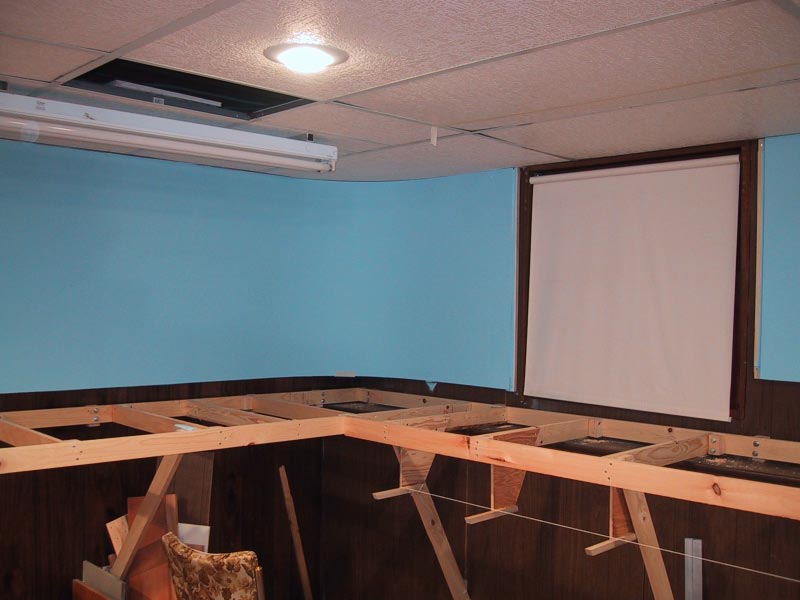
2. 12/31/01 First benchwork, shelf brackets

The removable section in the corner between Midstate Recovery Systems and Cains is based on a piece of 3/4 inch plywood which slides into wood channels on each side.  There are hard stops at the back, and toggle clamps underneath to hold it so the rails are precisely aligned.
4. 2/26/02 The removable section.

In this overview of freshly glued down ties, you can see the ties for the second siding next to what is now the Midstate Recovery siding - that second siding never got as far as rail.

5. 5/24/02 A lot of ties glued down.

I use insulation displacement connectors, which are very reliable if you use them only on the type and size of wire they're rated for. The heavy red and black wires are my #10 track bus. The smaller red and black are #18 track feeders. The orange and brown pair were going to be the #12 accessory bus, current plan is they will be a separate power bus heading from my command station (which is on a shelf under Cains) to the N scale layout.  At the time I choose the wire, it still wasn't clear that I wouldn't end up running older O scale equipment that drew a lot of current, which is why I choose the heavier wire.

6. 3/8/03 Wiring.

Building the second leg of the layout.  This view looks from Cains down toward the corner with Tighe and the transload track.

7. 9/16/04 More bench work.

I got impatient and reused a bit of old plywood with homasote glued to it for sub roadbed for the main track behind Cains.  That made it harder to tie into the preferred 3/4 ply sub roadbed.  The second problem is the sub roadbed was positioned for the Elmira Industrial plan, and the Corning Industrial plan needed it in a slightly different place, so I had to remove about 4 feet of it.  The plastic tube coming out of the plywood and curving into the wall is for feeding the cab bus through into the ceiling and on to the radio base station.

8. 9/16/04 Adjusting roadbed to the new plan.

When I did both the Elmira and Corning Industrial plans, I had access to a large format printer with the caveat that I bring my own paper.  So I could print the plan out on 3'x4' paper sheets full size.  Taping in place and running over the lines with a pounce wheel made it easy to transfer the plan to the plywood.  The track closest to the aisle is the Cain's siding, which will be cookie cuttered to allow lowering it an inch.


9. 10/17/04 Transferring plan to plywood.

Here's the Cains siding cookie cuttered out and lowered 7/8 inch. If you look really closely at the sub roadbed just where it separates from the main plywood, and again two risers closer to the foreground, you'll see I had to route the thickness of the plywood down to 1/2 inch for a foot or so to make the two vertical curves fall where I wanted them to. In the background you can see the sub roadbed for what was the Wegman's siding on the Corning Industrial plan (now the Tighe siding), elevated 1/2 inch with a strip of 1/2 inch plywood. I used a belt sander to get a nice long taper on the end, and the curve around the back corner is a series of short pieces with shallow angles on the ends which make the curve when put together.

10. 11/19/04 Cains siding cookie cuttered.

The homabed at the yard throat. Lots of cutting and fitting. The little dots are all the brads sticking up that I used to hold it in place while the glue dried - they'll be pulled out later.

11. 11/20/04 The homabed at the Corning Industrial yard throat.

Sanding the homabed can be tedious.  I got impatient this time and did it with the belt sander. Works quite well with relatively fine sand paper, a vacuum attached to control the dust, a bubble level stuck to the top (that round white thing), and some restraint. The odd thing in the upper left is a belt cleaning tool - it unclogs the sandpaper, and unclogged sandpaper makes everything go faster. You do need to be careful, and not press at all but just let the weight of the sander to the work while you worry about keeping it level and moving so you don't make dips and wobbles. It's way faster than the long piece of sandpaper on a 2x4 approach I used before.

12. 12/4/04 Sanding the homabed.

The original part of the layout is handlaid code 125 rail on wooden ties. The new part is Atlas code 148 flextrack. Needless to say, they're not the same overall height. It took some time and a lot of trial and error to get the homabed tapered down just enough to line up the rail head. The damage to the paint on the old rail is from the rail bender. It's not really noticeable from a normal viewing angle, but I'll touch it up one of these days. The speckly paint on the flex track is from a painting experiment that didn't go quite so well.

13. 12/4/04 Tricky alignment job.

I primed the homabed (and everything nearby) to seal it. I had white primer on hand, so that's what I used.  Gray would have been a better choice.  Pretty much every switch in this picture had to have a bit trimmed off at least one leg.

14. 12/13/04 Laying Atlas flex track and switches
That second siding I pointed out the ties for in photo 5 above meets it's demise.  The remaining siding was Cornell Brothers Agway on the Corning Industrial plan, and is now Northeast Container on the No-Name plan.  The jog visible in the distance was originally justified by the second track, I'm figuring out how to place buildings so as to make it visually "obvious" why the track jogs.

15. 2/13/05 Tearing out the ties for the second siding.
In the Elmira Industrial plan, the access hole in the corner was inside a building. In the Corning Industrial plan, it had the Cornell Brothers Agway track extending over it.  So I made a removable hatch to cover the hole.  The hatch registers against the near side of the hole, and in the back in the corner there's a cleat with a couple springs pushing against the hatch to keep it from wiggling around.  The screw eye near the front edge will be hidden by bushes. It's a handle to make it easy to lift the front edge, get a hand under it, and lift the whole thing out.  Since the end of the spur is going to be completely weed covered I didn't bother with homabed, ties, or ballast. That's just 1/2 inch homosote with rail spiked directly to it. The whole mess is sealed with gray paint. The track on the hatch is unpowered, since only a little over a car length of track is on the hatch there's no reason for a loco to ever get down there.

16. 8/5/05 Access hatch.

17. Screen wire for scenery at Cains.

The plans at one point called for a curved switch leading out onto a second peninsula covered with industry.  It seemed like a good idea to see if I could actually build a curved switch that worked before proceeding, so I did.  I drew up the centerlines in cad, printed out a full sized plan and glued it to a piece of 1/8" plywood.  I glued PC board ties to that, and after a lot of rail bending, filing, fitting, and soldering I had a turnout that worked pretty well.  And then I changed the plan to not need it.

18. 1/10/06 Curved switch done and works.

Not shown in this series of photos is the benchwork and track for the portion of the Corning Industrial's yard along the back wall - around the curve to the right in the photo below.  The only part remaining to be constructed was the second peninsula.  This is what the yard throat area looked like at the point at which doubts set in and eventually the plan changed.

19. 3/19/06 Corning Industrial yard

Even though I was very exciting about the new plan, it was a horrible feeling to rip up track and remove benchwork.  Especially given my glacial construction pace.  But it had to be done.  This photo shows the same corner as the above photo, with a lot of track removed and the benchwork around the corner removed.  The following photo shows the homabed being scrapped up.

20. 7/4/07 Demise of the Corning Industrial, converting to a shortline.
21. 7/6/07 Scrapping up lots of homabed.
Old stuff removed, ready to make progress on the shortline.  The horrible feeling went away at this point, replaced by enthusiasm for the new plan.  You can see the remnants of the curved yard homabed.  The heavy pencil lines are the new track alignment.

22. 7/6/07 Starting on new track.

The new switch for Cains is in in this photo.  I like the new Cains alignment much better than the old one.  Also note that the team track siding had the homabed tapered down to plywood level, to make it a bit lower than the main track.

23. 12/2/07 Main track in.


24. 4/5/11 Feeders ready to solder to new track.

Rather than show the current state of the No-Name at the tail end of this already too long post, I'll follow up with another post with current photos.